Indy Suspension Build

GeoTracker90

Adventurer
OK, so this will be my on going build thread. I'll document my attempt at building a home grown, air bagged independent suspension expedition trailer. Why? Well I'm not sure why, but I do know that I LOVE to build trailers and this style of suspension is a challange to design, build and implement. It's also an excuse to build another trailer, and it keeps me out of trouble.

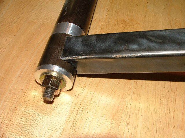
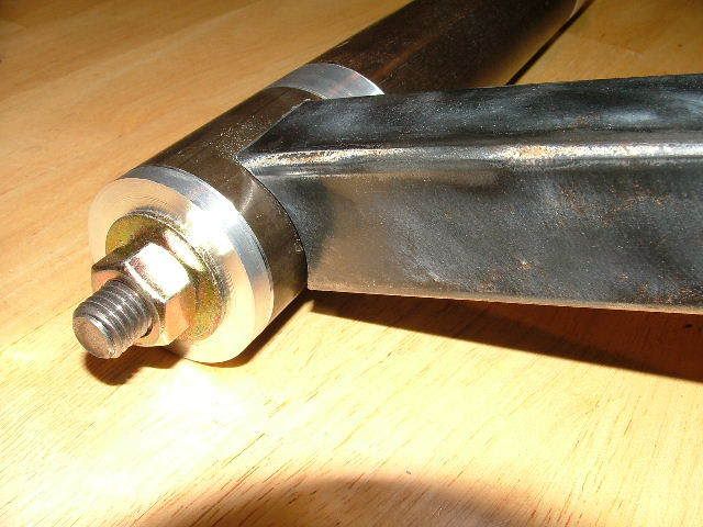
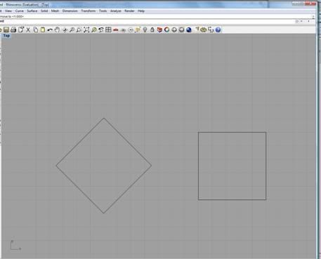
So far I have a pretty good idea of the design that I want to follow as I build this critter. So far I have the bushings gathered up and I'm currently working on building a jig to align them as I weld the trailing arms together. Tonight I was able to fire up the old lathe (1945 Sheldon) and put a couple discs of aluminum on a strict weight reducing diet. One lost just a little more weight than the other though.

DSCF4607.jpg


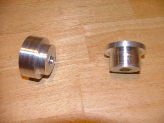
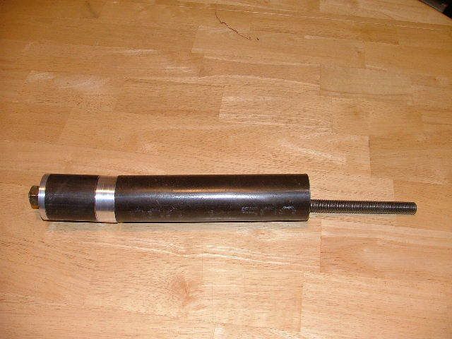
I need to get some more shop time and make them a set of twins. I bored out the center hole to 9/16" so accept the threaded rod that will hold the assembly alligned as I work on it.

DSCF4608.jpg


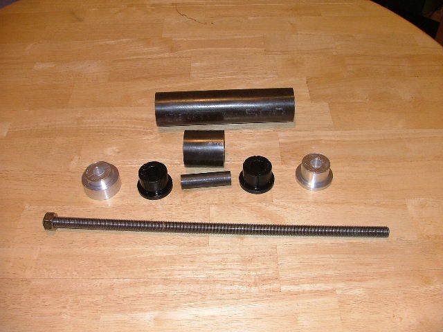
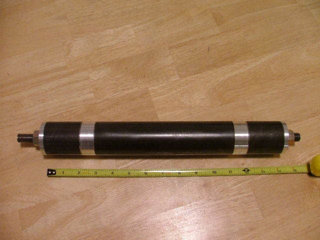
I can't wait to get the other set done so that I can finish assembling the skewer.

DSCF4611.jpg


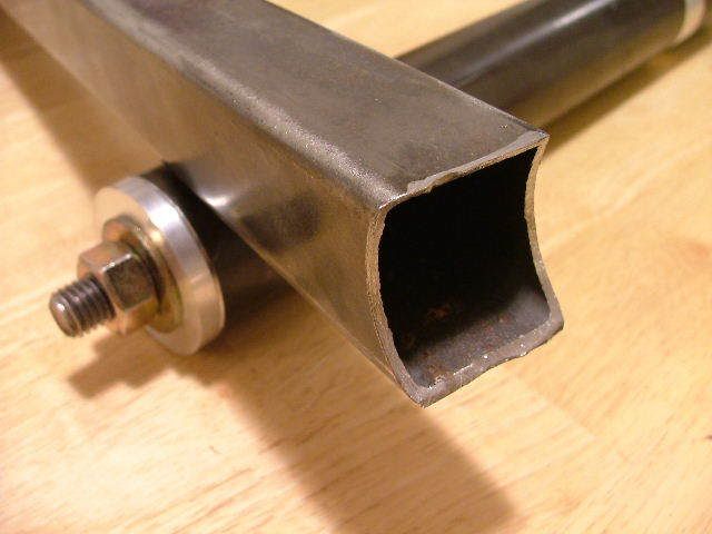
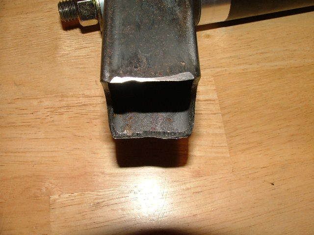
With any luck I'll order a couple spindles in the a.m. and they will show up before the weekend. I guess I had start looking at buying some tubing for the arms as well. I'll post more as the build continues.

Mike
 

GeoTracker90

Adventurer
ntsqd said:
bump, inquiring minds & all......

Thanks for the bump, but unfortunatly there won't be any progress on it this weekend. I'm selling a toyota flat bed on Saturday and I'm going to deliver it to the guy a couple hundred miles away.

I guess if I get a real early start I might have time Saturday night to fire up the lathe for a little while. Well, I'll have to see how things go.
 

GeoTracker90

Adventurer
Well I was able to spend a little more time with the lathe and turned out the other two alignment bushings.

DSCF4649.jpg


From the outer edge of the one bushing shell to the other is almost bang on 14". I guess I now need to get going and round up the next batch of parts. The spindles, spindle tubes, threaded tube adapter, two bushing shells w/ threaded studs, and the tubes for the trailing arm itself. After that will come the brackets for attaching the trailing arms to the frame cross member and the frame itself.

My 90 day anniversary at work is coming up. Pray that I get a raise.

:xxrotflma
 

GeoTracker90

Adventurer
Ok, since this got bumped back up to the top I'll give an update.

I had a piece of scrap 1-1/2" square tube with a 0.083" wall kicking around that was just begging to get cut up. I broke out the 2" hole saw and the drill press and promply found out what I was affraid of. I need a bigger and better drill press.

I'm not able to hold the tube in my drill press vise and use the hole saw at the same time. Also the drill press motor would lug down and the hole saw would stall periodically. None the less, I was able to at least make the cut, although not with any kind of accuracy. Accuracy being paramount to how I want to proceed with this build.

DSCF4668.jpg


DSCF4669.jpg


DSCF4671.jpg


DSCF4673.jpg


So it looks like I'll need to bribe one of the machinists at work to cut my tubes on the mill for me. If I treat them real nice I might even be able to convince them to write a little G-code and do it on the CNC machine. Then the center to center distances of each tube would be the same.

As far as the tube goes I'll either end up using some 1-3/4" DOM tube with a 0.120" wall or some 1-1/4" square tube with a 3/16" wall thickness. If I use the square tube I will have it rotated 45* from flat before the cuts are made. This will make the cuts enter and exit the tube on the corners of the square instead of the flats. I anticipate that this will provide for a better weld joint as a greater portion of the weld will be in the verticle plane and less in a horizantal plane. I hope that makes sense.

With any luck I'll be ordering the spindles in a week or two and then I'll focus on sourcing the tube that the spindle will be pressed and welded into.

I'll post up again next time I make some progress on this.

Mike
 

ntsqd

Heretic Car Camper
Even though I usually get slightly better accuracy I never plan on a hole saw being better than +/- 1/16"

I don't see any advantage in turning the square tubes 45* If you were using torsion bars then maybe at that end it would be worth something. Since you're not and there will be a bending moment applied to them I would orient them flat. If all of the loads are parallel & perpendicular to the flats of the tube, a square tube is a better choice than a round tube. If the loads come in at all sorts of odd angles then a round tube is a better choice.
The way to look at this is to compare the tubes to an I-beam. Laid with the flanges flat, spanning a gap, and load placed in the middle is the common use of an I-beam and is where it is the strongest. It's strength is in the flanges and the distance between those flanges, not in the web between the flanges. A square or rectangular tube, laid flat, takes a loading the same way as the I-beam does. Turned 45* there is no pair of flanges oriented to best support the load, so then a size calc becomes much uglier and the "wet thumb in the wind" method has a much larger error potential.

That more than you wanted to know, or already knew?
 

GeoTracker90

Adventurer
ntsqd said:
Even though I usually get slightly better accuracy I never plan on a hole saw being better than +/- 1/16"

I don't see any advantage in turning the square tubes 45* If you were using torsion bars then maybe at that end it would be worth something. Since you're not and there will be a bending moment applied to them I would orient them flat. If all of the loads are parallel & perpendicular to the flats of the tube, a square tube is a better choice than a round tube. If the loads come in at all sorts of odd angles then a round tube is a better choice.
The way to look at this is to compare the tubes to an I-beam. Laid with the flanges flat, spanning a gap, and load placed in the middle is the common use of an I-beam and is where it is the strongest. It's strength is in the flanges and the distance between those flanges, not in the web between the flanges. A square or rectangular tube, laid flat, takes a loading the same way as the I-beam does. Turned 45* there is no pair of flanges oriented to best support the load, so then a size calc becomes much uglier and the "wet thumb in the wind" method has a much larger error potential.

That more than you wanted to know, or already knew?

My thoughts on turning the square tubes 45* is centered around the forces that each surface of the square will experience.

If the tubes are in a standard, flat orientation then the top surface will see compression forces, the bottom surface will see tension forces and the two sides will see bending forces. The above statement is making the assumption that the force is directed in a verticle plane.

If the tubes are rotated 45* then the two top surfaces will see compression forces, and the two bottom surfaces will see tension forces. Again this statement is making the assumption that the force is directed in a verticle plane.

My last reason for turning the tubes 45* deals with the tube to bushing shell joint. With the tube turned 45* the weld joint has a greater percentage of the weld available to handle forces in the verticle plane.

Link.jpg


With all of that said I need to give the disclaimer that I am not a structural or mechanical engineer, but I am a thinker and I do try and research things before I attempt them. If any body has professional expertice in these things, please weigh in and let me know if I'm on the money with my reasoning or if I've overlooked something.

Mike
 

Ireland

Adventurer
Great build idea in my opinion so keep it up...
I think turning the square tube the way you are thinking is a great idea but one problem I might think of is that it would likely be more difficult to machine the ends as accurately as it would be just leaving them flat...
This could be solved with making a jig to hold it in the drill press though.
All the ideas i see for home built suspensions are making me want to do one myself in the near future...
Again keep up the good work...
 

GeoTracker90

Adventurer
The problem with accurately machining the ends with the tube turned 45* disappear with some v-blocks and a CNC milling machine. I haven't approached the subject at work yet, but I think that I can get approval to have one of our machinists help me out with this. Time will tell though.

V-blocks.jpg


Haas.jpg
 

Rezarf <><

Explorer
You're on the right track bud. Keep it up. Personally, I would keep it flat, I think the forces on a trailer are not as extreme as on a vehicle, a good wall thickness will pick up the strength you need. I think fitment and leg work to get them right cocked at that angle will produce marginal strength advantages/to the work put into it.

Just my .02, if you have access to that CNC stuff, it can't hurt in going for it! :D

I am really enjoying your thread, thanks!

Drew
 

GeoTracker90

Adventurer
The other advantage of cutting these on the CNC, either angled or flat, is that I will have two pieces as close to identical as possible. I'll post up more as I get further along with this.

Mike
 

Forum statistics

Threads
187,466
Messages
2,894,839
Members
228,400
Latest member
rpinkall1
Top